APPLIED INDUSTRIAL CONTROL SOLUTIONS
ApICS LLC.
BENDING LOSS CALCULATIONS
BRIAN T. BOULTER, HARRY W. FOX
© ApICS ® LLC 2000
ABSTRACT
This report presents a mathematical model for estimating roll-by roll bending losses and tension build-up required in strip material as it bends and straightens while traveling through a network of powered and unpowered rolls in a process line. The total horsepower required for the drag and drive bridles in strip process lines depends not only on process throughput parameters, such as tension set points and process line speed, but on the summation of the various losses encountered along the line. Methods are described for continuous tracking of strip fiber deformation on a roll-by-roll basis beginning at the process line entry section. Such an analysis of bending losses is desirable when encountering rolls of varying diameters, for which the steady-state analysis of the literature is no longer valid.
INTRODUCTION
An example strip process line shown in Figure 1, in which the material passes from an unwinder section, through a number of sections consisting of rollers of various sizes, to a terminating winder section. The straining of the material as the strip bends on the rolls and straightens between the rolls can require additional unrecoverable work by the drive motors, particularly whenever portions of the strip fibers undergo plastic deformation. Thus, a certain amount of bending loss, often reflected added tension build-up, can occur at each of the rollers.
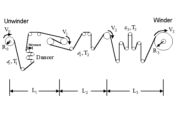
Figure 1. Example strip process line
The total horsepower required for the drag and drive bridles in metal strip process lines depends not only on process throughput parameters, such as tension set points and process line speed, but on the summation of the various losses encountered along the line. A serious underestimation of the process line tension needs could be disastrous, in that the desired product specifications can not be met. Extravagantly over sizing the bridle drives, on the other hand, can increase the cost without any net advantage.
An analysis of the tension distribution along the process line is usually undertaken to determine the most favorable horsepower distribution, since it is desirable to utilize all the horsepower specified. The installed power, which needs to be kept to minimum, corresponds to the power needed for strip deformation, bridle input and output tension differences, and to account for mechanical losses.
This report presents a mathematical model for estimating the tension change that takes place as the metal strip bends and straightens during its travels through the network of powered and unpowered rolls in the process line. The tension build up due to bending is often neglected for rolls not found in a tension-leveler section of the process line. The model described in this report shows how bending-loss estimates may be incorporated in analyses of tension needs beginning at the process line entry section.
The strip goes through the bending process as it approaches a roll and a straightening process as it departs from the roll. The bending can be visualized as strip deflection with increasing curvature (decreasing radius of curvature). The fibers on the outside of the curved strip surface elongate, while the fibers on the inside of the curved surface (i.e., those which will contact the roll surface) compress. The degree of elongation and compression symmetry depends on the level of average (axial) tension, which controls the amount of center fiber movement.
Figure 2 shows an example bridle section, consisting of four rollers controlling the direction in which the strip moves. The subsequent bending of the strip can be characterized by forward and reverse bending directions. For example, if the bending direction in which roller 1 (exhibiting velocity V1 ) moves the strip is called forward bending, then the bending direction in which roller 2 (exhibiting velocity V2 ) moves the strip is called reverse bending.
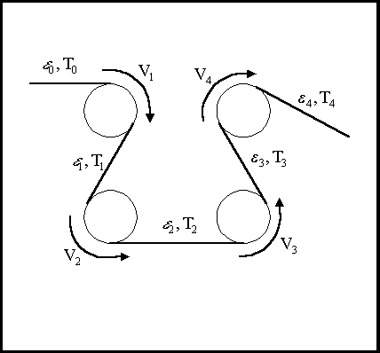
Figure 2. Example bridle (4-section) in a process line
Other investigators, primarily interested in tension leveling, have studied this bending process as it would apply to the steady-state case of passing over and under a series of rolls of the same radius. The bending losses reported represented that for the n-th pass from one roll to the next identical roll of reverse bend. Kinnavy [1] considered bending combined with tension high enough to elongate the center fiber, for an elastic, perfectly-plastic material. Patula [2] , also for an elastic, perfectly-plastic material, considered bending with tension stress levels from zero to yield and identified five distinct (steady-state) behaviors, from completely elastic to completely plastic. Misaka and Masui [3] presented an experimental equation for the effective radius of curvature (when the strip does not conform with the roll) and an analysis of combined bending and tension for material exhibiting a linear work-hardening stress-strain characteristic. Smith [4] considered the increase in bending moment required when deforming an elastic, perfectly-plastic material as a measure of the added roll force due to the plastic work when straining the outside and inside fibers during bending.
The purpose of this paper is the remove the steady-state limitation inherent in the previous work, by presenting a computer model that simulates the bending and straightening process on a roll by roll basis. The model will be useful in the design of tension bridle systems.
The balance of this report is divided into the following five chapters (followed by the bibliography):
- Chapter 1 : Nomenclature
- Chapter 2 : Describes the basic features of the bending process and presents thefundamental equations to be used by the models in subsequent chapters
- Chapter 3 : Presents a bending-loss model from the literature [2] which is based on a set of algebraic equations that are valid for the special case of steady-state bending over rolls of identical diameter in alternating forward andreverse directions. The basis of the model is developed through a specificexample illustrating a series of three bending and straightening operations.
- Chapter 4 : Presents a numerical model of the bending process which is consideredmore general and more flexible than an algebraic model requiring steady-state conditions to be valid. The material deformations and any losses are determined and updated on a roll-by-roll basis.
- Chapter 5 : Conclusions
CHAPTER 1
NOMENCLATURE
|
a,b,c |
elastic-plastic positions normalized to half thickness, t/2, after bending |
|
a¢
, b¢
|
elastic-plastic positions normalized to half thickness, after straightening |
|
A, Au |
strip cross-sectional area (stretched, unstretched) [ft2] |
|
D |
roll diameter [in.] |
|
E |
modulus of elasticity [lbf / in.2] |
|
L,LU |
length (stretched, unstretched) [in.] |
|
M |
bending moment [ft-lbf] |
|
MY |
bending moment when outer fibers reach yield stress [ft-lbf] |
|
N |
number of element across strip thickness in numerical model |
|
Pbend |
power required for bending [ft-lbf / s] ( 1 [hp] = 550 [ft-lbf / s] ) |
|
D
Pbend |
power change (output - input) of roll due to bending [ft-lbf / s] |
|
t |
strip thickness [in.] |
|
T |
tension [lbf] |
|
D
Tbend |
tension change (output - input) of roll due to bending [lbf ] |
|
V,VU |
velocity (stretched, unstretched material) [ft / s] |
|
Vin |
velocity at entrance or input [ft / s] |
|
Vout |
velocity at exit or output [ft / s] |
|
w |
strip width [in.] |
|
x |
dimension in which strain occurs, measured along strip length [in.] |
|
y |
dimension measured across thickness from center fiber [in.] |
|
D
yP |
depth of plastic deformation from surface [in.] |
| |
|
|
a
|
stress normalizing (dimensionless) parameter ( = T / (s
Y w t) ) |
|
a
0 |
initial value of stress normalizing parameter, before 1st bend |
|
a
i |
stress normalizing parameter after i-th bend |
|
a
¢
i |
stress normalizing parameter after i-th straightening |
|
b
|
strain normalizing (dimensionless) parameter ( = e
B,max / e
Y ) |
|
e
|
strain [in. / in.] |
|
e
¢
|
normalized strain in numerical model ( = e
/ e
Y ) |
|
e
B |
stain due to bending only in numerical model [in. / in.] |
|
e
¢
B |
normalized strain due to bending only in numerical model ( = e
B / e
Y ) |
|
e
B,max |
maximum longitudinal strain [ in. / in. ] ( = t / 2r
) |
|
e
C |
center-fiber strain [in. / in.] |
|
e
¢
C |
normalized center-fiber strain in numerical model ( = e
C / e
Y ) |
|
e
T |
total strain in numerical model [in. / in.] |
|
e
¢
T |
normalized total strain in numerical model ( = e
T / e
Y ) |
|
e
U |
permanent elongation in numerical model [in. / in.] |
|
e
¢
U |
normalized permanent elongation in numerical model ( = e
U / e
Y ) |
|
e
Y |
yield strain [in. / in.] ( = s
Y / E ) |
|
l
|
stress normalizing parameter from the literature ( = a
) |
|
m
|
stain normalizing parameter from the literature ( = 1 / b
) |
|
r
|
radius of curvature [in.] (when used in bending equations) |
|
r
,r
u |
strip density (stretched,unstretched) [lbm / ft3] (used in mass balances) |
|
s
|
stress [lbf / in.2] |
|
s
¢
|
normalized stress in numerical model ( = s
/ s
Y ) |
|
s
Y |
yield stress [lbf / in.2] |
CHAPTER 2
MODELING THE BENDING PROCESS
The modeling of the bending process is divided into two parts. Pure bending of strip sections with a high degree of symmetry is presented first. This results in a simplified model which estimates the deformation behavior of the individual fibers across the strip thickness. This determines the portion of material fibers undergoing plastic deformation, typically those on the outside and (sometimes) inside of the bending radius. Then the extent of the elastic core and the boundaries between the plastic and elastic regions can be identified, and the stress profile across the strip thickness can be calculated.
The second part of the modeling in this chapter is more macroscopic in nature. Mass, torque, and power balances are presented for a given roll, for which the individual fiber strain and strain behaviors are described by averaged or integrated quantities.
Model Development -- Pure Bending With Symmetric Sections
Consider the strip subjected to bending effects alone. The following restrictions on the geometry of the strip and on the manner of loading are assumed:
- Strip is straight (i.e., not twisted)
- Material is homogeneous
- Constant rectangular cross section
- Cross section has a longitudinal plane of symmetry (see Figure 1)
- Resultant of the applied loads lies in the plane of symmetry
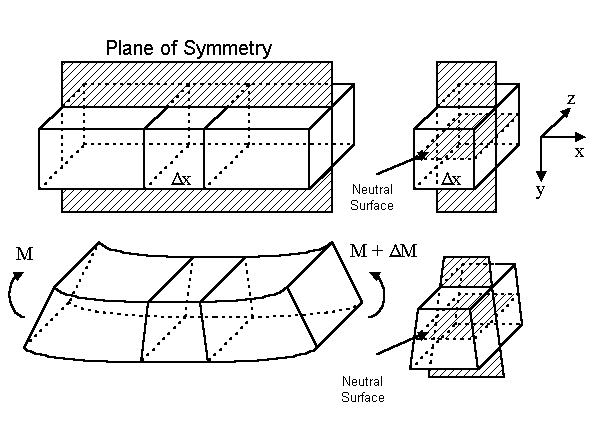
Figure 3. Strip element
Figure 3 shows an element of the strip, unbent in the top two diagrams and bent along the plane of symmetry in the bottom two diagrams. To examine the effect of pure bending, it is assumed that the element is loaded only by pure couples, M and M + D
M , as indicated. Except in the neighborhood of externally applied loads, any small portion D
x of the element undergoes similar bending deformations as adjacent portions.
For this ideal case, the cross-sectional areas originally perpendicular to the longitudinal bending (x-axis) remain plane and perpendicular to the longitudinal direction after bending. Any line (fiber) originally parallel to the longitudinal bending (x-axis) becomes curved -- an arc of a circle with a radius equal to the radius of curvature.
The real world is not ideal, however, and deformations occur perpendicular to the longitudinal plane of bending. That is, in the direction of the z-axis is Figure 3, the fibers located above the neutral surface elongate while those below the neutral surface shorten. For example, if a fiber strains longitudinally an amount equal to e
X , it will strain an amount equal to e
Z = -m
e
X in the z-direction, where m
is Poissonís ratio for the material. Crossbow -- curvature about the longitudinal x-axis in the direction of strip travel -- results if yield stresses are exceeded in the transverse z-axis direction [5]. This curvature due to Poissonís effect shall be neglected, however, in following analysis, in which the longitudinal strain throughout the strip length and thickness is related to the distance in the y-axis direction from the neutral surface.
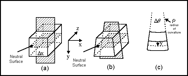
Figure 4. Small portion of strip element
Figure 4 shows the small portion D
x of the strip element presented earlier in Figure 3. The undeformed portion shown in Figure 4(a) becomes the deformed portion of (b), with the curved shape along the longitudinal x-axis shown in (c). The strain at a distance y from the neutral surface can be found as follows:
- Let r
= the radius of curvature at the neutral surface
- Arc length at y is related to the arc length at the neutral surface and strain at y:
 (2-1) (2-1)
 (2-2) (2-2)
For rectangular (symmetrical) cross section, the linear variation of longitudinal bending strain e
X with the distance y from the neutral axis, described by Eq.(2-2), can be represented graphically as shown in Figure 5(a), for the case of zero or negligible average strip tension. The graph is oriented for increasing values of y rising vertically, towards the outside fibers of the strip width which are in tension; distances oriented downward would be towards the inside fibers of the strip width which are in compression.
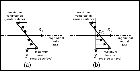
Figure 5. Strain versus distance from neutral surface
Applying an average tension (to the strip cross section) elongates the center fiber and shifts the strain distribution, causing less compression in the inside fibers but more tension in the outside fibers, as illustrated in Figure 5(b). The center fiber elongation is represented by e
C in the figure. The relationship of e
C to the average tension T depends on the stress-strain curve for the material; i.e.,
 (2-3) (2-3)
where s
(
e
)
represents the stress as a function of the strain and the integral is carried out over the cross-sectional area.
For a elastic, perfectly-plastic material the stress-strain curve can be drawn as in Figure 6.
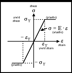
Figure 6. Stress-strain curve for an elastic, perfectly-plastic material
The stress distribution across the strip thickness will depend on two factors: (1) the shape of the stress-strain curve and (2) the amount of bending and, hence, the amount of strain. Figure 7 shows some examples, from purely elastic bending in (a) to nearly purely plastic bending in (c), for the case of zero to negligible center fiber elongation (i.e., relatively low average tension level). Elastic bending occurs typically over large radius rolls (relatively low curvature) with small gauge strip. As the roll radius decreases (i.e,, increasing curvature) and the strip gauge increases, the inner and outer fibers become plastic, but the central core remains elastic. In the limit, as the roll radius approaches zero and the strip gauge approaches infinity, the central elastic core shrinks to zero and the bending becomes fully plastic.
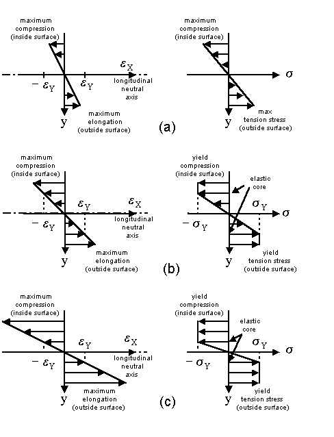
Figure 7. Stress (symmetrical) versus distance from neutral surface
The symmetrical stress distributions of Figure 7 are valid whenever the average strip tension is relatively small, such that the stress due center fiber elongation is much smaller than the yield stress (s
C << s
Y ). A variable D
yP equal to the depth of plastic deformation from the outside and inside surfaces can be defined for such symmetry. The size of the elastic core can be related to this new variable, therefore, since the elastic core would lie in the range
 (elastic core) (2-4) (elastic core) (2-4)
Smith [4] considered the increase in bending moment required as the elastic core shrinks due to an increase in plastic deformation D
yP . The added roll force due to bending required can then be determined, since roll force can be calculated from the applied bending moment.
The bending moment, M , at which a point on the outer fibers of the material reach the yield stress s
Y is given by the following analyses -- one for pure elastic bending and one for elastic, perfectly-plastic bending:
- For pure elastic bending (i.e., no plastic region; see Figure 7(a)):
e
B,max £
e
Y (2-5)
 (2-6) (2-6)
 (2-7) (2-7)
 (2-8) (2-8)
 (2-9) (2-9)
 (2-10) (2-10)
Some other forms of the pure-elastic bending moment are :
 (2-11) (2-11)
 (2-12) (2-12)
Elastic, perfectly-plastic bending:
(width of plastic region = D
yP ; see Figure 7(c))
 (2-13) (2-13)
 (2-14) (2-14)
 (2-15) (2-15)
 (2-16) (2-16)
 (2-17) (2-17)
 (2-18) (2-18)
 (2-19) (2-19)
where: MY = maximum pure elastic bending moment (defined above)
Pure plastic bending:
(width of plastic region, D
yP = t/2)
 (2-20) (2-20)
where: MY = maximum pure elastic bending moment (defined above)
Thus, by comparing the results above, it can be seen that for pure plastic bending -- i.e., at full plasticity -- the bending moment is 50 percent greater than that for the maximum pure elastic bending -- i.e., the amount required to initiate plastic flow. The variation of the bending moment with the outer fiber strain is shown in Figure 12. The relationship is shown in non-dimensional form by dividing the applied strain by the strain at yield, e
Y , and the resulting bending moment by the bending moment at yield, MY .
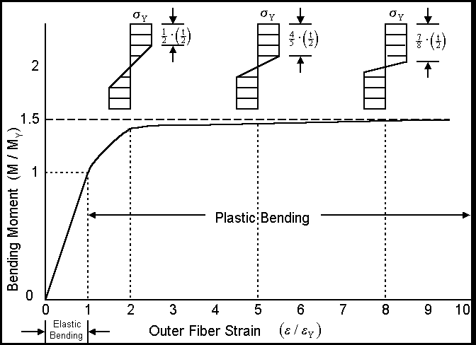
Figure 8. Bending moment as a function of outer fiber strain
When the average strip tension is large enough to call for relatively large center fiber elongation, however, the stress distribution across the strip thickness becomes unsymmetrical, as shown in Figure 9. Bending moment calculations can be calculated for each unsymmetrical distribution, but such calculations can not be normalized into a single convenient relationship, as was the case for the symmetical distributions.
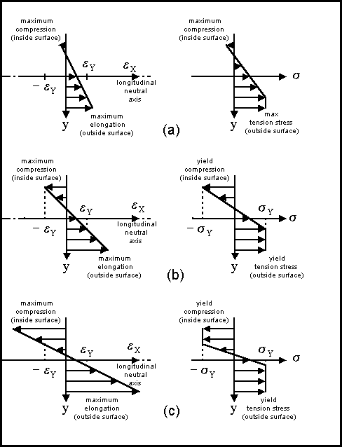
Figure 9. Stress (unsymmetrical) versus distance from neutral surface
Model Development -- Roll mass, torque, and power balances
Assumptions
- uniform cross-sectional area and material properties of strip:
- occurs only longitudinally
- perfectly-elastic, perfectly-plastic stress-strain curve (see Figure 6)
- elastic region is given by Hookeís law
 (2-21) (2-21)
- single lump for the mass balance of unstretched material
- uniform stretch (strain, e
) that of the center fiber
- uniform tension T (stress, s
) averaged over thickness
- input, output, and roll variables defined in Figure 10
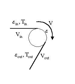
Figure 10. Input and output variable for a roll
The mass of material in any given section is constant, whether unstretched, stretched, or compressed. The density, cross-sectional area, and length, however, depends on the state of elongation. These quantities are related as follows [6]:
r
AL = r
uAuLu = r
uAuL/(1+e
) (2-22)
r
A = r
uAu/(1+e
) (2-23)
Extending the mass balance concept to the moving strip results in the following mass flow balance, which is based on a mass balance for a time interval D
t :
(mass flow in) D
t = (mass flow on roller) D
t = (mass flow out) D
t
Dividing through by the time interval D
t :
(mass flow in) = (mass flow on roller) = (mass flow out)
 (2-24) (2-24)
For constant (unstetched) strip density and cross-sectional area:
 (2-25) (2-25)
When considering powered rolls, the strain and stress change while the strip conforms to the curved surface, since the strip creeps the controlled amount to establish a tension change [4]. The present investigation considers only unpowered rolls, however, for which there is no change in stress and strain in contact with a roll. The changes in stress and strain considered in this investigation occur as the strip approaches a roll and again as the strip departs from a roll. Thus, following summarizes the assumptions made for this analysis:
- strain (constant) while in contact with the roll = e
- change in strain prior to roll contact,

- change in strain after roll contact,

Because the strain is very small, the following approximation based on the binomial theorem can be made for each of the terms in the previous equation:
 for e
<<1 (2-26) for e
<<1 (2-26)
Applying this to the mass flow balance equation yields:
 (2-27) (2-27)
Solving for the input velocity in terms of the roll velocity:
 (2-28) (2-28)
 (2-29) (2-29)
 (2-30) (2-30)
Solving for the output velocity in terms of the roll velocity:
 (2-31) (2-31)
 (2-32) (2-32)
 (2-33) (2-33)
The power (i.e., time rate of change of energy or work) for a roll to overcome the input and output bending losses can be found from the following power balances. For completeness, a difference in tension while in contact with the roll is included, where T is the strip tension when the strip makes contact on the input side and T¢
is the strip tension when the strip leaves the roll on the output side. In this investigation, however, it is assumed that (D
T)roll = T¢
- T = 0 .
Approaching the roll, prior to contact
(power out) = (rate of work by roller) + (power in)
 (2-34) (2-34)
 (2-35) (2-35)
 (2-36) (2-36)
 (2-37) (2-37)
Departing from the roll, after roll contact
(power out) = (rate of work by roller) + (power in)
 (2-38) (2-38)
 (2-39) (2-39)
 (2-40) (2-40)
 (2-41) (2-41)
Combined (approach + departure)
 (2-42) (2-42)
 (2-43) (2-43)
 (2-44) (2-44)
Due to bending only, total (in + out), and assuming D
e
in = D
e
out = D
e
/2 :
 (2-45) (2-45)
 (2-46) (2-46)
In terms of the dimensionless parameters:
 (2-47) (2-47)
 (2-48) (2-48)
 (2-49) (2-49)
where the dimensionless terms A and B are calculated, under steady-state assumptions (to be discussed in the next chapter), as follows in the literature [2]:
|
Region |

|

|
|
A |
0 |
0 |
|
B |

|
0 |
|
C |

|

|
|
D |

|

|
|
E |
0 |
0 |
CHAPTER 3
ALGEBRAIC (STEADY-STATE) MODEL FROM THE LITERATURE
PROPRIETARY
CHAPTER 4
NUMERICAL MODEL
PROPRIETARY
CHAPTER 5
CONCLUSIONS
A numerical model was developed for estimating roll-by roll bending losses and tension build-up required in strip material as it bends and straightens while traveling through a network of powered and unpowered rolls in a process line. It provides for the calculation of strip fiber deformation on a roll-by-roll basis beginning at the process line entry section, without restricting the analysis to steady-state or identical forward-reverse bending paths. Numerical model results agreed with results obtained from less-flexible algebraic-equation-based models, derived in this report and found in the literature.
BIBLIOGRAPHY
[1] Kinnavy, M.G.,"Recent Developments in Tension Leveling ", Iron and Steel Engineer, Nov. 1972, pp 67-72.
[2] Patula, E.J., "The Tension-Roller-Leveling Process -- Elongation and Power Loss" Journal of Engineering For Industry Vol 101, No.3, August 1979, pp 269-277.
[3] Misaka, Y., Masui T., "Shape Correction of Steel Strip by Tension Leveller", Journal of Japan Society for Technology of Plasticity, 17 (1976), p988, in Japanese. English version received June 22, 1977.
[4] Smith, R. P.,"Flatness Control in Coiled Plate - Design and Operation of Lukensí Wide Cut To Length Line ", Proceedings of 1996 AISE Spring Convention, April 22-23, 1996, pp 291-314.
[5] Kinnavy, M.G.,"Design Considerations in Tension Leveling Systems ", Iron and Steel Engineer, Oct. 1990, pp 33-42.
[6] Carter, W.C., "Reducing Transient Strains in Elastic Processes" , Control Engineering Mar. 1965. pp. 84-87.
[7] Byars, E.F., Snyder, R.D., Engineering Mechanics of Deformable Bodies , 2nd Ed., International Textbook Company, 1969.
|