You may have purchased stereo drivers and when looking at the
manufacturers published specs you feel that the values don't seem
correct. Maybe you purchased an inexpensive driver for testing
purposes and had no specs at all. You will find here the methods and
formulas to determine the parameters needed to design boxes and
filters.
When wanting to measure the parameters of any transducer, a
minimum of instruments are required for the task. You will need a
multimeter with voltage and Ohms measurement capabilities. You will
also need a frequency generator that is variable from about 20Hz to
20KHz. A stereo linear Amplifier. Other accessories include resistors one
of 1000 Ohms and one of 10 Ohms. These instruments are the minimun
required to determine any usefull parameters.
Microphones and anechoic chambers will not be discussed.
Before performing any mesurements, any driver should be broken
in (played at moderately high volume for an extended period) prior
to these mesurements as the parameters change once broken in.
Re
DC resistance is determined with an Ohms meter
connected to it's terminals.
Le
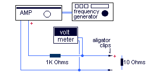
Le is mesured using a small setup consisting of
every item in the instruments list, here is the setup
diagram.

The 10 Ohms resistor is used to calibrate the
setup so it should be a very precise and linear resistor.
With
the resistor connected to the end connectors or aligator clips, set
the frequency generator at approximatly 1000 Hertz. Ajust the gain
on the Amplifier and the frequency generator until the AC voltmeter
reads 10 volts. If you feel your amplifier or any component in your
setup is not as linear as it should, reajust the gain with the
resistor at every frequecy you will use to make your readings.
To
find the Le you must set the frequency at the drivers highest
usable frequency. By removing the 10 Ohms resistor and placing the
driver at its place. The reading on the voltmeter will be what's
called the driver's impedance magnitude (M) for this
frequency. It is then used in this formula to find Le .

You can also find Le with the
following calculator using the values you have found with the setup.
Ce
The value of Ce is determined with Re and Le
with the following formula.

You can also find Ce with the
following calculator using Re and Le.
Fs
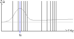
Finding the value of fs is quite simple.
Simply note the frequency at the apex of the impedance peak(Zmax).

Qms
To find Qms, the formula requires you to find the
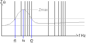
value of R0 first. R0 is the value of Zmax at fs over Re.

Then the product of Re and the square root of
R0 will give you the value of R1.

Then above and below fs, note the frequencies
where the impedance is equal to R1 Those values will be f1 and f2 as
in the following diagram.

Qms is then found with the following formula.

Qes
Qes is found with the following formula using Qms
and R0.

Qts
Qts is found with the following formula using Qms
and Qes.

Mmd
To find the moving mass of the driver you will
first need to know the fs of the driver as shown above. You will
then need a calibrated weight(M') to be attached on the driver's
cone, usually a piece of clay. Once the weight(M') is firmly
attached to the cone find the driver's new fs(fs').
You can then
find Mmd with the following formula;
Mmd = M' /
(fs/fs')2 - 1
Cms
Cms requires fs and Mmd in the following
formula;
Cms = 1 / (2pfs)2 *
Mmd
Sd
The driver's effective piston Area is foud with the
following formula.
Sd = pr2
Where "r" is the radius of the
cone.
Vas
By taking great care in finding Cms you can find
Vas with the former with this formula.
Note that Sd must be in
centimeters.
Vas = Cms * De * Cs2 *
Sd2
In the preceding formula "De" represents the
density of air in grams per cubic centimeter, tipically 0.0013 grams
per cubic centimeter. "Cs" is the speed of sound in air, here in
centimeters per second. Under normal circumstaces, at audible
frequencies, this value is about 34400 centimeters per second.
|